Electrical Design
The electrical design for the Golfer Bot consisted of various circuits designed to allow for proper interaction of the bot with its competition environment. Therefore, circuits were created to provide power to the bot, actuate movement for the bot, sense external inputs, and provide a visual indication of the bot's status to observers. Sections describing these various components of the electrical design can be found below.
Power Management
Please click on the above image for more information.
A LM2940 5V regulator was used to provide power to the Golfer Bot.
Motor Drive
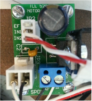
Please click on the above image for more information.
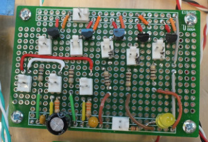
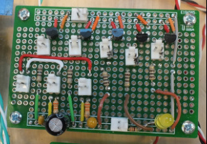
To power the drive motors, a TLE 5206 H Bridge was implemented.
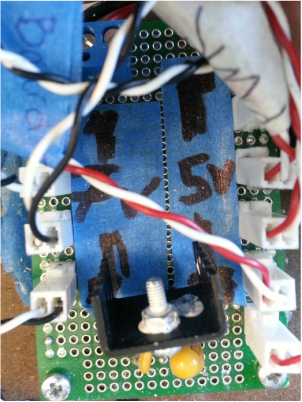
Servos
Please click on the above image for more information.
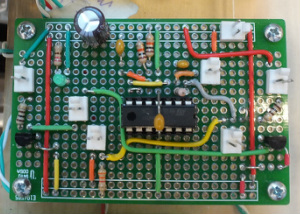
Four servos were implemented in the Golfer Bot, and all four worked in concert to actuate the shooting mechanism.
Beacon Sensing
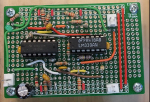
Please click on the above image for more information.
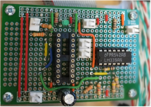
To detect an IR beacon in the game, a phototransistor was wired through a transresistive amplifying stage, a hi pass filter, and a comparator with hysteresis.
Beam Break Detection
Please click on the above image for more information.
A beam break detection circuit consisting of a phototransistor and a simple comparator circuit with hysteresis was used to detect whenever a Nerf ball had entered the Golfer Bot from the resupply depot in the game.
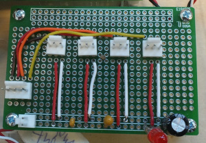
Infrared Ball Requesting
Please click on the above image for more information.
To request additional Nerf balls during the game, 5 IR LEDs were wired in an array to pulse at a given frequency to dispense balls from the resupply depot.
Bump Sensors
Please click on the above image for more information.
Various limit switches were employed to provide the Golfer Bot with feedback when it backed up against the resupply depot or the shooter had been fully reloaded.
Game Status LEDs
Please click on the above image for more information.
To indicate the game status, two jumbo LEDs were connected to digital outputs on the E128 microcontroller.
E128 Connection Pinout
Please click on the above image for more information.
A complete listing of the pin assignments on the E128 microcontroller can be found here.
