Beacon Sensing Circuit
Please click on the above image to see a higher resolution circuit diagram.
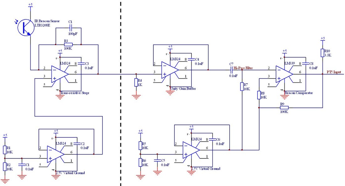
The Beacon Sensing circuit for the GBot was contained on two separate protoboards, and it was designed to detect two different beacon signal square waves with possible frequencies of 50 Hz and 70 Hz. The first board contained the schematic to the left of the black dashed line. This circuit combined a virtual ground at 2.5V with a trans resistive circuit with a gain of 100K. The gain stage of the trans resistive circuit also incorporated a small (100pF) capacitor in parallel with the gain resistor which would not amplify the high frequency noise present in the system.
This board then passed that signal to the second board, which contained the schematic to the right of the black dashed line. This board featured another virtual ground at 2.5V, a unity gain buffer, a hi-pass filter, and a comparator. The hi-pass filter was designed with a corner frequency of 159 Hz, which created well defined peaks at each of the rising edges of the beacon signal. These peaks, which were centered at 2.5V, were then passed through to a comparator centered at 2.5V with a hysteresis band of ~0.5V. Therefore, the output of the comparator changed when the input voltage raised above 2.27V or dropped below 2.72V. Given the ambient conditions and dimensions of the playing field this circuit provided a robust, reliable signal that could be monitored using an input capture line on the E128 microcontroller.
This board then passed that signal to the second board, which contained the schematic to the right of the black dashed line. This board featured another virtual ground at 2.5V, a unity gain buffer, a hi-pass filter, and a comparator. The hi-pass filter was designed with a corner frequency of 159 Hz, which created well defined peaks at each of the rising edges of the beacon signal. These peaks, which were centered at 2.5V, were then passed through to a comparator centered at 2.5V with a hysteresis band of ~0.5V. Therefore, the output of the comparator changed when the input voltage raised above 2.27V or dropped below 2.72V. Given the ambient conditions and dimensions of the playing field this circuit provided a robust, reliable signal that could be monitored using an input capture line on the E128 microcontroller.
